Knife Edge Support

Design of the transfer of vertical loads into a steel sheet pile according to the German National Technical Approval Z-15.6-235 (2021)

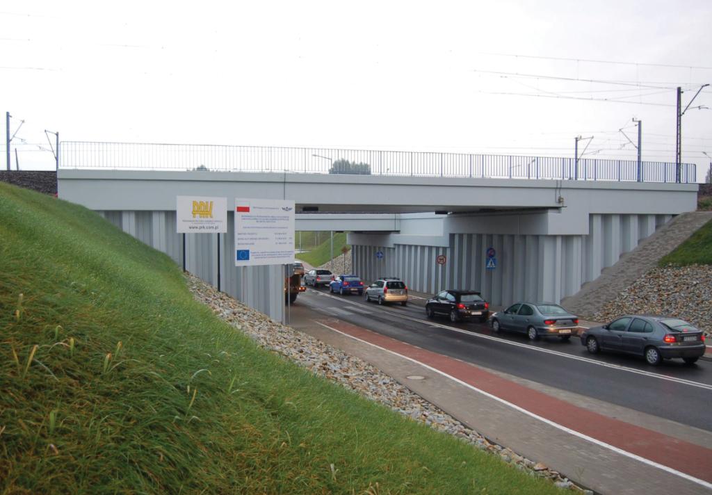
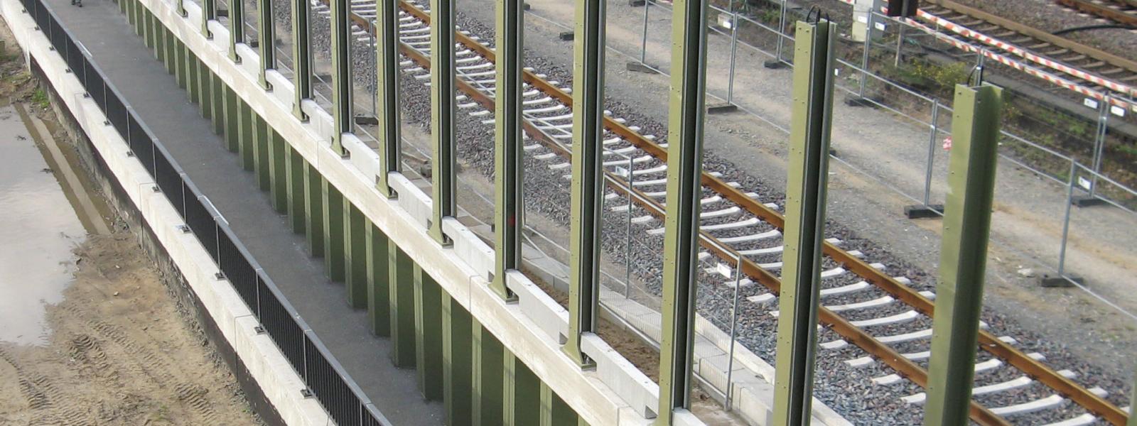
Steel sheet piles are commonly used for permanent and temporary structures, such as quay walls and retaining walls on road and rail infrastructures. They are typically subjected to horizontal loads caused by earth and water pressure, with minor vertical loads transferred to the walls. However, in some cases, sheet piles must resist significant vertical loads, such as those caused by cranes on quay walls or traffic on bridge abutments.

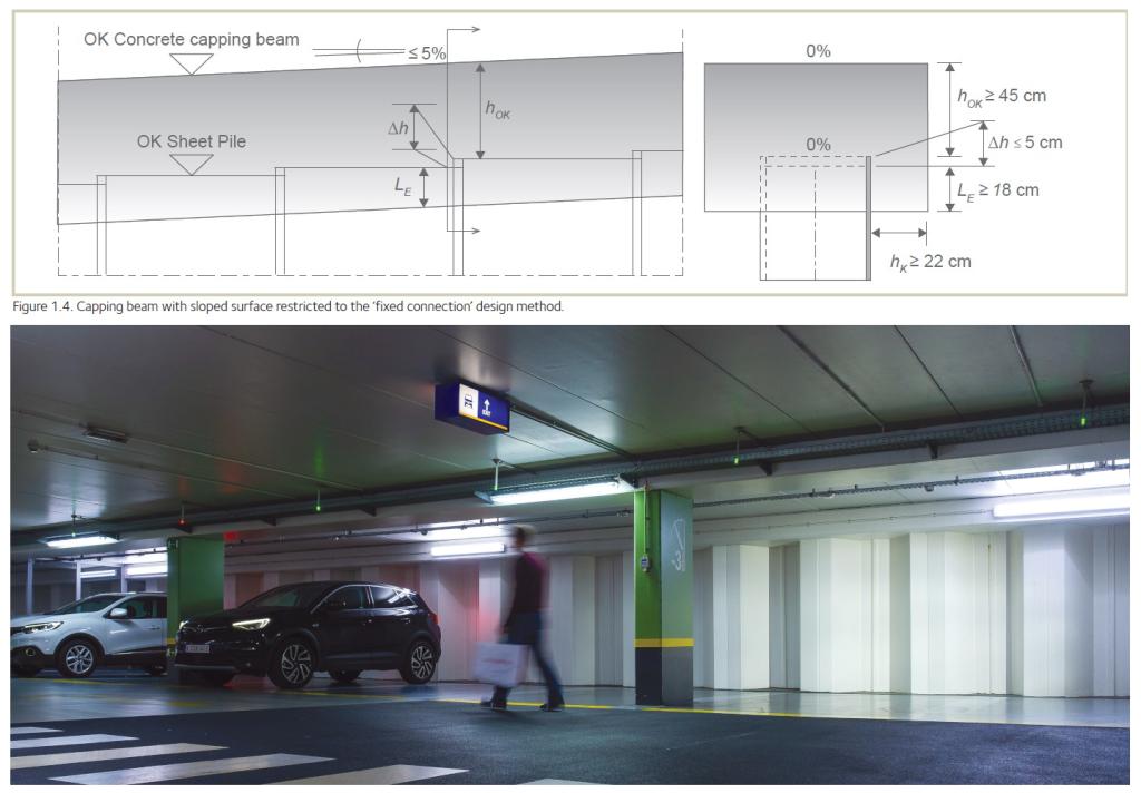
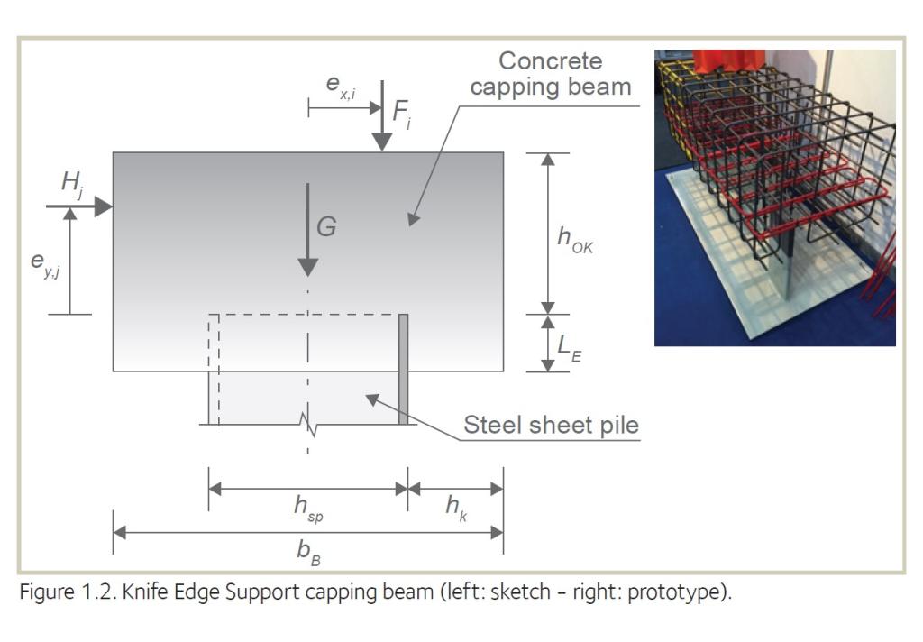
The Knife Edge Support (KES) method offers a cost-effective solution for transmitting horizontal and vertical loads to the ground through a steel sheet pile, without requiring additional welding on-site. This design concept is particularly useful for quay walls, underground car parks, bridge abutments, and locks.

The German authorities have granted National Technical Approval (NTA) to this design, which is based on extensive research and full-scale testing by ArcelorMittal's R&D department and the University of Darmstadt. The tests analyzed load transmission and compared behavior to a standard reinforced capping beam.

Design software VLoad

Pause Play

The NTA-approved capping beam can support a vertical load of 1475 kN/m, an increase of 136% compared to the maximum load allowed by German standard DIN 1045 or European code EN 1992.

The KES method has been tested and approved for static and non-static vertical loads, as well as static horizontal loads. Static action refers to actions that don't significantly accelerate the structure or its members. Non-predominantly-static action, defined in German standards as "nicht vorwiegend ruhende Last", refers to non-static loads that may lead to fatigue after repeated actions but aren't considered dynamic loads. Dynamic action causes significant acceleration and requires specific design considerations.

 Scope of application

When designing a capping beam on top of a steel sheet pile wall according to the NTA, two cases should be distinguished

  • simply supported capping beam. The sheet pile wall is slightly embedded into the concrete capping beam but does not transfer any bending moment to the sheet pile.
  • restrained capping beam. The sheet pile wall is sufficiently embedded into the concrete capping beam so that it is able to transfer bending moments to the sheet pile.

The NTA considers horizontal capping beams. Capping beams with a slope up to 5% in the longitudinal axis of the wall (see Figure 1.4.) can be designed with the ‘fixed connection’ method. However, the top and bottom surface of the capping beam in a plane perpendicular to the plane of the wall must be horizontal.

Capping beam types

It is necessary to differentiate two types of reinforced concrete capping
beams when designing a KES. Following geometrical requirements apply
to both types (see Figure 1.2.).

  • minimum height of the capping beam above the top of the sheet pile
    hₒₖ ≥ 45 cm
  • minimum recommended concrete cover6)
    cₘᵢₙ ≥ 40 mm
    tolerance Δc ≤ ± 15 mm
  • concrete lateral overhang
    hₖ ≥ 22 cm