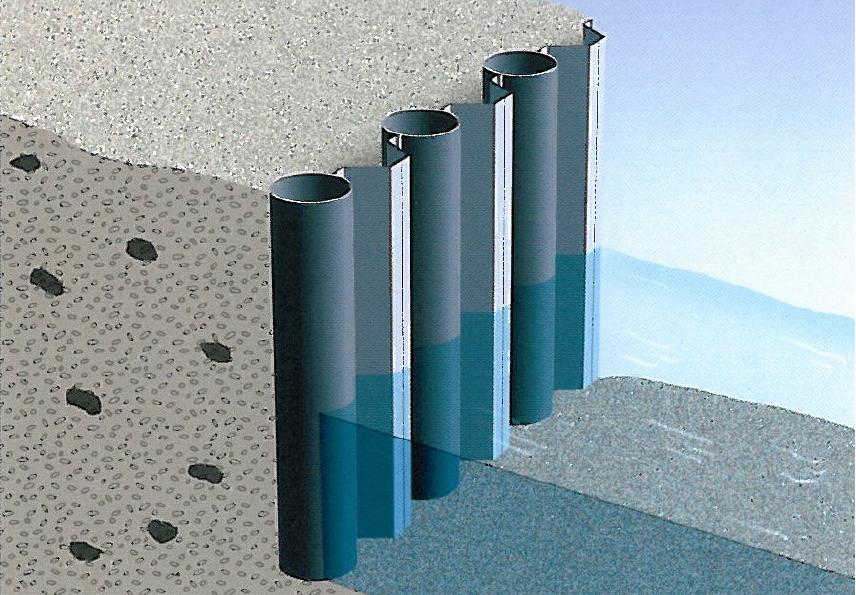
AZ sheet piles in combined walls

Exceptional performance of AZ sheet piles in combined walls

ArcelorMittal appointed Liege University's Structural Steelwork Department to conduct a detailed study to demonstrate the excellent behaviour of AZ sheet piles when used as intermediate sheeting in combined walls. This study included not only laboratory testing but also numerical simulations. It demonstrated that these sheet piles can in fact withstand a hydraulic head of more than 50 m without failing. It can therefore be said that a method for verifying AZ sheet piles based simply on the theory of elasticity can offer only a very uneconomic approximation of their actual behaviour. 

(Section 8.1.4.2 of EAU1996 calls for verification of intermediate sheeting for water heads exceeding 4 m!).


This document is available in English, French, and German.

Download

en English AMCRPS_AZ-Sheet-piles-in-combined-walls_2014.pdf
Pause Play

Laboratory testing 

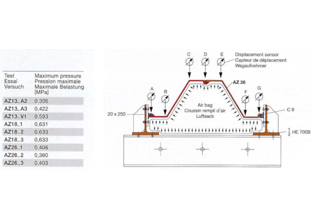
In all, nine large scale tests were carried out on AZ-13, AZ-18 and AZ-26 sections. A sample sheet pile length of 1 metre was chosen. The inside face of the casing plates was PTFE-coated to ensure an in-plane displacement pattern of the sheet piles. Compared to site conditions, where some part of forces is always transmitted longitudinally, this arrangement provides a good safety margin. 

A rubber airbag was used to exert loading as realistically as possible. Maximum test pressures applied are shown in Table. S355GP grade steel was used for the tests. 

Except in the case of the AZ-26 sections, no sheet pile failure was achieved in the tests (the airbag burst first). It may therefore be assumed that actual failure pressures for the AZ-13 and AZ-18 sections are even higher than the maximum test pressures.

Numerical simulation 

Based on the test results, a numerical model was calibrated at the Structural Steelwork Department using FINEL-G finite element software. This tool is particularly suited to the consideration of geometrical and material-related non-lineari-ties.

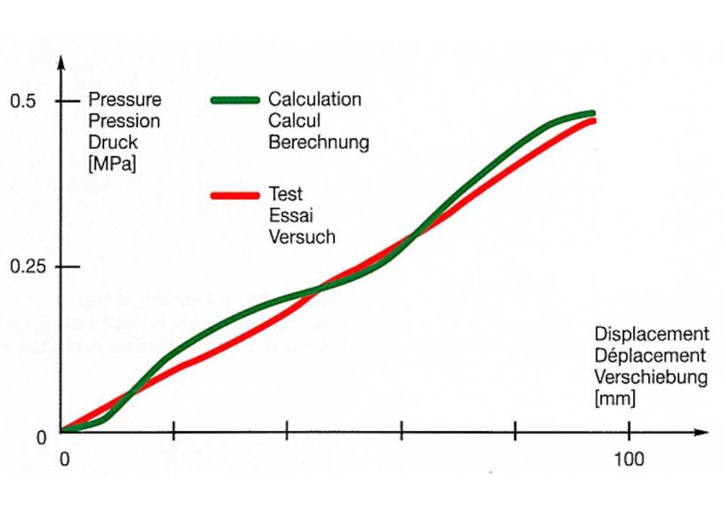
Similarly, interlock swing and strain hardening of the steel were taken into account. Figure 3 reveals the total agreement between the simulation and test results in the most usual load range (hydraulic head <= 40 m). 

Numerical simulation results provide an insight into the excellent behaviour of AZ sheet piles resulting from their geometry. Plastic deformation is chiefly concentrated in corners B and F of the sheet pile and is lesser at the interlock zones. This is notably confirmed by the test results. 

Design 

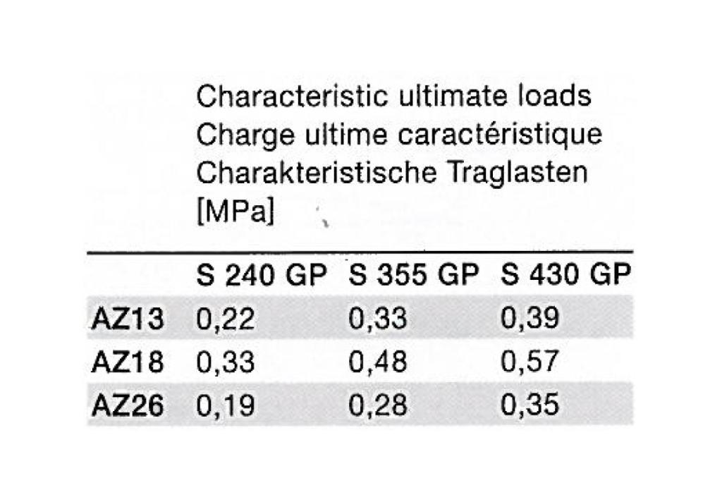
Characteristic ultimate loads for AZ intermediate sheet piles with different yield strengths. These are based on the test results. For the capacities shown in the tables to be applicable, the connection with the primary supporting elements must be in accordance with good practice and there must be a suitable safety factor.

Summary 

  • The lowest failure pressure was 0.36 MPa (= 36 m hydraulic head);
  • Load-displacement behaviour is far better than that of double and triple U-piles; 
  • Under very high pressures, the majority of the plastic deformation is concentrated at sheet pile corners B and F and not at the interlocks; 
  • High pressures are increasingly transferred as normal tensile stresses (membrane effect). 
  • Because of their geometry, AZ intermediate sheet piles remain unaffected by driving deviations of a magnitude corresponding to good construction performance. 
    ...

The abovementioned advantages of AZ sheet piles make them ideal intermediate elements for combined walls not only for structural but also for economic reasons (system width up to 1340 mm).