Underground Car Parks | Germany
Comparison Study | Cost-Benefit Analysis

- Underground Car Parks | Germany

AskBoris
Introduction
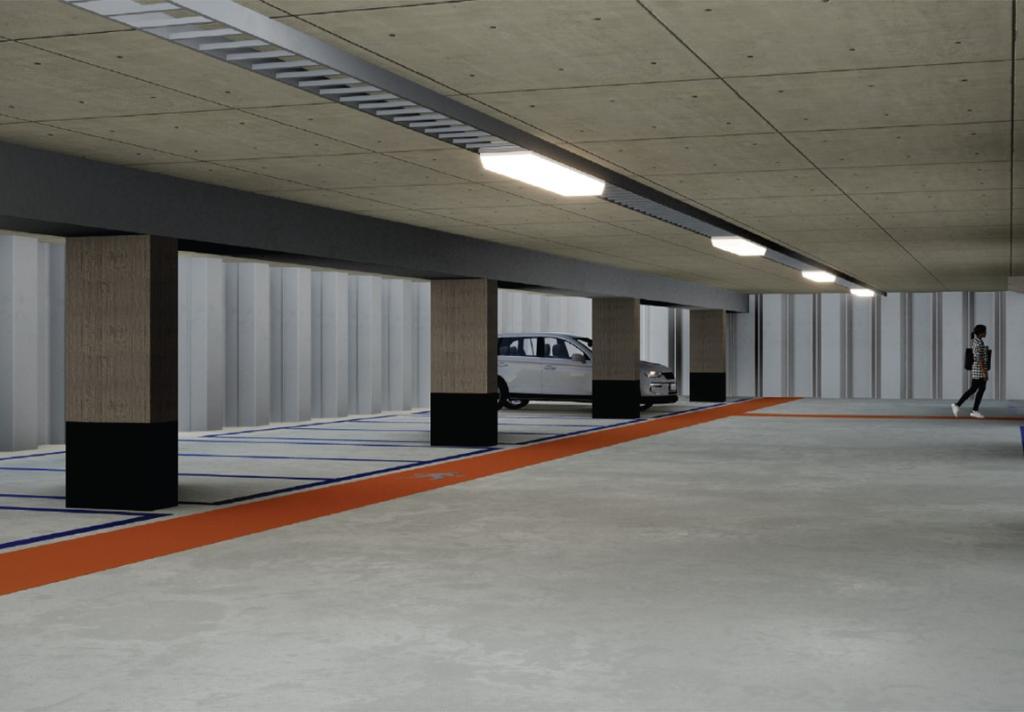
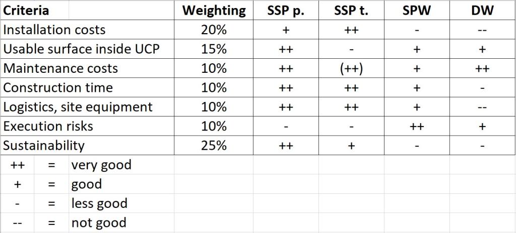
This study examines the use of steel sheet pile (SSP) walls in the construction of underground parking facilities, focusing on their effectiveness in different regional conditions. The first part compares various wall construction methods for a two-level underground parking project in northern Germany, evaluating factors like cost, construction speed, and sustainability.


Download the document
Boundary Conditions
Geometry/Structural Components
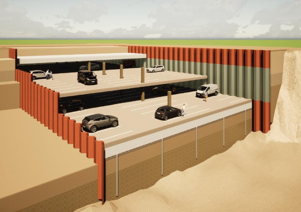
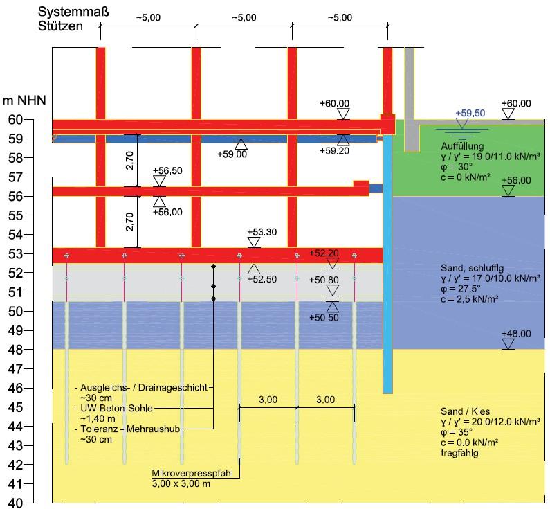
The designated construction site has a specified area of 28 x 50 metres. The new building will have a ground surfce of 28 x 28 metres. The underground car park will consist of two levels, each with a clear ceiling height of 2.70 metres.
In this example, it is assumed that the groundwater table is located just below the surface level. As a result, the construction of the excavation and the underground car park will require a base slab made of underwater concrete. This base slab prevents water intrusion into the excavation from below during construction.
Additionally, the slab, along with the micropiles embedded within it, will resist the uplift pressure caused by dewatering the excavation. For the structural design, a 1.40-metre-thick concrete base slab is assumed, including a 30 cm levelling/drainage layer. To account for excavation tolerances, an additional 30 cm is subtracted.
It should be noted that the underwater slab and the micropiles have no influence on the results of the system calculations, as the boundary conditions remain consistent across all systems.
Construction Phases
The following construction sequence is specified for the execution of the works:
1. Construction of the retaining wall, depending on the chosen construction method:
a. V1 - Permanent sheet piling:
- Predrilling
- Driving of the sheet piles
b. V2 - Temporary sheet piling:
- Drilling of loosening holes for the driving track
- Driving/ vibrating of the sheet piles
c. V3 - Secant pile wall:
- Installation of the bored piles, including concreting and reinforcement (further steps only after the concrete has cured)
d. V4 - Slurry wall:
- Construction of the slurry wall, including concreting and reinforcement (further steps only after the concrete has cured)
2. Installation of the stiffening layer at +59.00 m NHN (preceded by: excavation to +58.50 m NHN + parallel lowering of the groundwater level to +58.00 m NHN)
3. Underwater excavation to +50.50 m NHN
4. Installation of UW concrete, including the levelling layer, buoyancy piles, and drainage layer, and dewatering of the construction pit to +50.50 m NHN
5. Concreting of the basement floor slab (undergound level 2), columns, and ceiling above U2, temporary bracing of the ceiling above U2 to the retaining wall (→ not applicable for "V2 - Temporary sheet piling"), and removal of the stiffening layer
6. Concreting of columns, ceiling above underground level 1, including the reinforced concrete connection to the retaining wall (→ not applicable for "V2 - Temporary sheet piling"), removal of the temporary sheet piles (V2)
Calculation assumptions
Loads
Upon completion of the underground garage, the superstructure will be constructed with 4 floors. The vertical loads resulting from this will be transferred to the ground through the external walls and columns. As a result, the retaining structures will also carry vertical loads in the final state, except for the temporary sheet piling. The vertical load is defined as a line load with Nk = 350 kN/m.
Due to the proximity of neighbouring buildings, the retaining wall is directly adjacent to the existing structures. The neighbouring buildings are founded on strip foundations.
The upper edge of the strip foundation is set at +58.00 m NHN, with a width of 1.0 m. The floor level of the neighbouring building is at +60.00 m NHN. The foundation load has been calculated, assuming the dimensions and materials of the existing building, with Gk = 350 kN/m.
Additionally, a load of pk = 5 kN/m² is applied at the ground level from the rear edge of the existing foundation. This covers the load from the self-weight of the floor slab and additional imposed loads.
| Variant | Designation | Wall Type | Chosen (LWall) |
| [-] | [-] | [-] | [m] |
| V1 | Sheet piling, braced, permanent | AZ 32-750; S 355 GP | 14.50 |
| V2 | Temporary sheet piling as excavation support | AZ 32-750; S 355 GP | 14.50 |
| V3 | Overlapping bored pile wall, braced, permanent | Ø 1,18 m | 14.50 |
| V4 | Slurry wall, braced, permanent | t = 1,00 m | 16.00 |
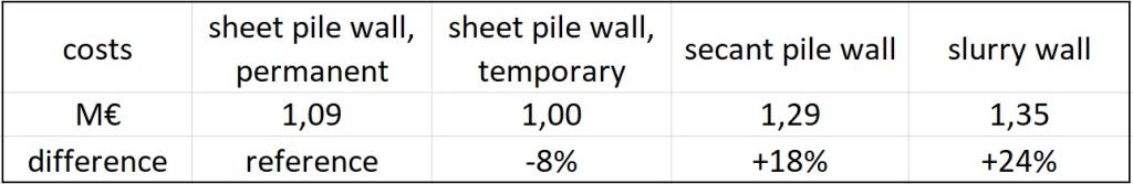
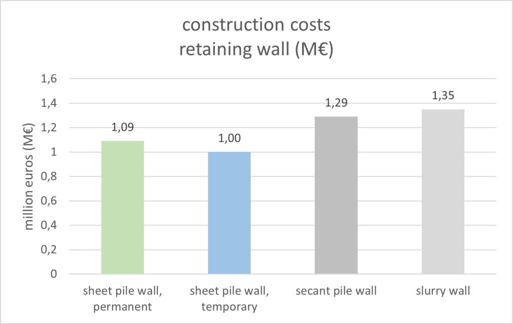
The temporary sheet pile wall is the most cost-effective solution. The difference is approximately 18% compared to the secant pile wall and about 24% compared to the slurry wall.
Conclusion