Underground car parks. Part 2 | Life Cycle Assessment
Detailed Design | The Netherlands

- Underground car parks. Part 2 | Life Cycle Assessment

AskBoris
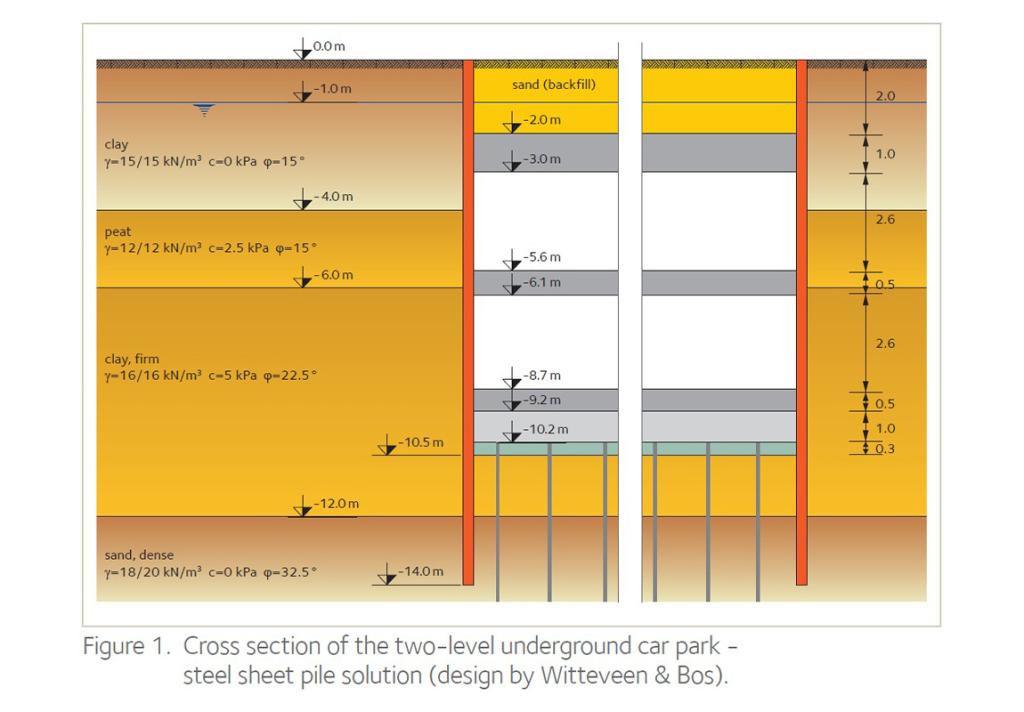
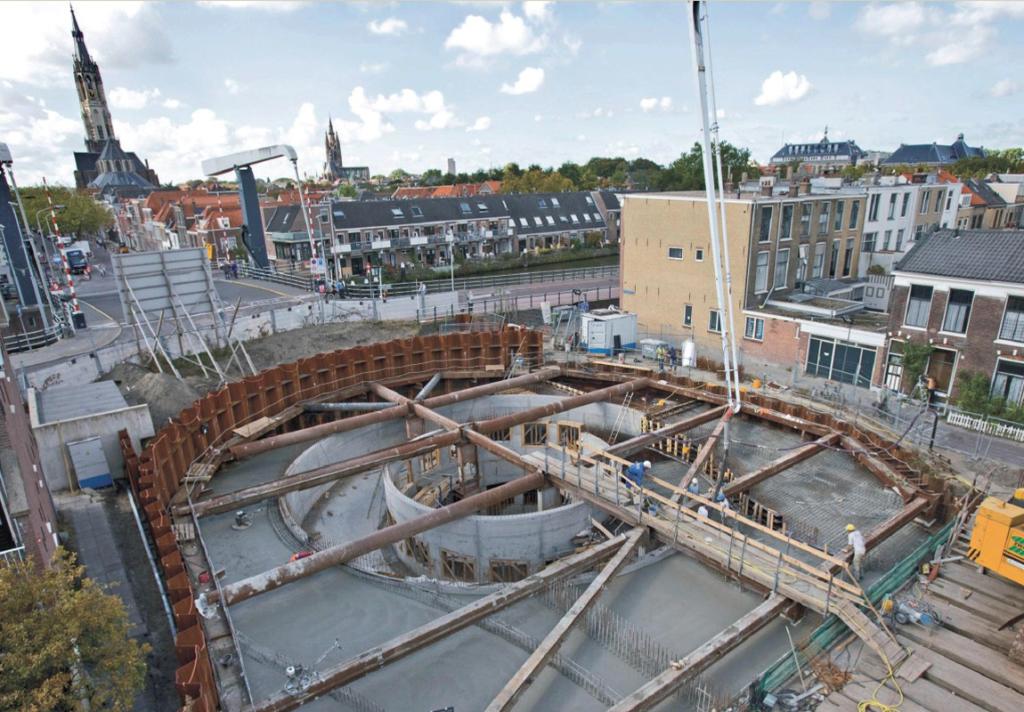
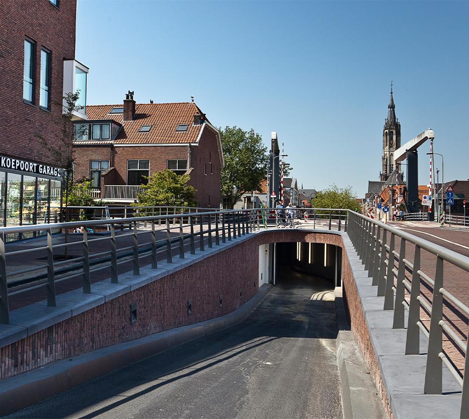
The technical and economic analysis of this case study was performed by the Dutch consulting engineers Witteveen & Bos for ArcelorMittal in 2020. The design assumptions were determined for a two level below grade underground car park in soil conditions that are typical for the region of Amsterdam in the Netherlands. The design assumptions were the same for the four alternatives. From an engineering point of view, such simplified assumptions for a soil can be used for a feasibility study or for a comparison of different alternatives.
ArcelorMittal emphasizes on the fact that Witteveen & Bos performed an objective and unbiased case study. The analysis is a purely hypothetical case study with its limitations on reliability on costs and techniques, since these aspects can be very dynamic in markets and different subsoils.
This case study is not a project specific design, therefore neither ArcelorMittal nor Witteveen & Bos can be held responsible for choices made in specific projects based on the design or conclusions of the report prepared by Witteveen & Bos.
The Life Cycle Assessment (LCA) was performed in-house by the R&D department in 2020, and peer-reviewed in 2020 by the Dutch independent research organisation TNO, acting as an independent expert. The conclusion of the reviewers is that the LCA report has been performed in a professional and unbiased way, and that the conclusions are exact. Key parameters were submitted to a sensitivity analysis that confirmed the basic scenario; the variation of the parameters did not reverse the results nor the conclusions from the basic scenario.
Download the document


Comparing the environmental impact of different solutions
For this type of application, an LCA is a reasonably fair and transparent method to compare different solutions and suppliers. Although not required by ISO and EN standards, an LCA is more accurate and realistic when it uses specific Environmental Product Declarations (EPDs) from the producers rather than generic data from databases.
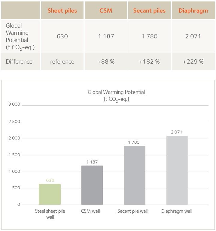
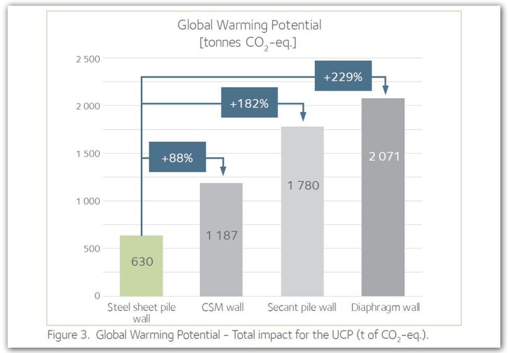
The choice of a solution shall consider several key indicators, the principal one being the construction cost (including the design). The key environmental indicator analysed in this case is the carbon footprint; its impact for the basic scenario is summarized in the graph below for a rectangular UCP about 250 m x 30 m.
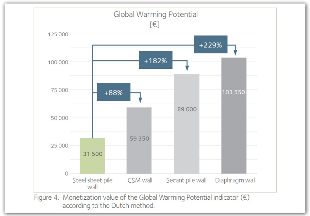
This indicator can be included in a scheme to choose the most sustainable solution (most economically advantageous tender), such as the monetization method used in the Netherlands which is based on multiple environmental indicators.
In this case study, the conclusion is that the EcoSheetPile™ steel sheet pile wall has the lowest carbon footprint, the difference being 88 % compared to the cutter soil mix wall (CSM), and much more compared to a secant pile wall and a diaphragm wall. A sensitivity analysis showed that modifying some key parameters did not impact significantly the gaps, and in no case reversed the result.
Introduction
The scope of the work from the Dutch engineering firm Witteveen & Bos was to design the four alternatives and to compare the overall construction cost of the walls, taking into account financial aspects linked to speed of execution and the return on investment (ROI), the end of life scenario where the structure should be demolished (whenever possible), and if applicable, the benefits of reuse or recycling of the structural elements.
The technical and financial aspects are dealt in detail in Part 1 of this brochure.
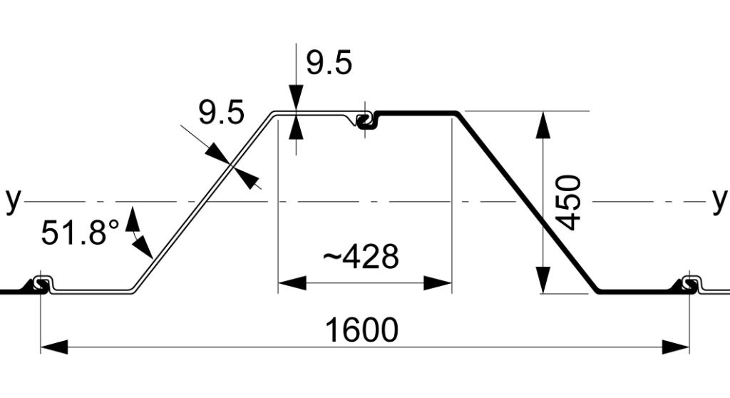
The sheet pile wall is designed with a 14.0 m long standard AZ 20-800 section, in steel grade S 355 GP. Using a higher steel grade would increase the resistance of the wall and consequently the safety on the steel stresses, but would not reduce the deflection / deformation of the wall, which is one key parameter in this case.
The CSM wall is 15.0 m high, with a thickness of 550 mm and reinforced with steel H-beams, whereas the secant pile wall is 14.0 m high with a diameter of the piles of 630 mm and with steel H-beams used as reinforcement of the main piles. The diaphragm wall is 14.0 m high and has a thickness of 800 mm.
It turned out that under the chosen conditions and assumptions, the steel sheet pile wall is the most cost-effective solution: around 40 % more economical than the cutter soil mix wall. The most expensive solution is by far the diaphragm wall, and the secant pile wall is slightly more expensive than the CSM wall. Despite the tremendous cost difference between the D-Wall and the other solutions in this specific case, the LCA covers the four alternatives to check if the carbon footprint might offset the financial weakness of one or another solution.
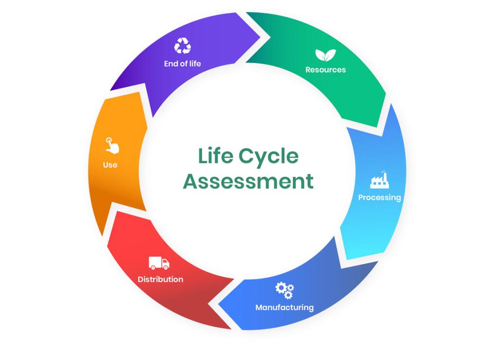
Life Cycle Assessment of Sustainable Structures
The Bill of Quantities obtained in the design project serves as the input for the Life Cycle Assessment.
The most sustainable structure can be determined in different ways. Several key environmental indicators can be used to compare the most sustainable solutions, such as the MKI indicator (ECI in English) in the Dutch monetization method. However, this LCA focuses on the Global Warming Potential (GWP) which is the main factor influencing the rise of the temperature on our planet. Other environmental indicators were analysed and show similar trends as the GWP, except for one indicator. The monetization method used in the Netherlands was chosen for this analysis.
The LCA was performed by the R&D department of ArcelorMittal in 2020, and peer-reviewed by independent experts from the Dutch research organisation TNO. The conclusion of the reviewers is that the LCA report has been performed in a professional and unbiased way, and that the analyses are correct.
The variability of key parameters can influence significantly some results; hence a sensitivity analysis of key parameters was also performed. The alternative scenarios confirm that for most of the parameters, their variation has a limited impact on the results, but never reversed the conclusions from the basic scenario.
Goal, scope and assumptions
Infrastructure description and assumptions
The design of the structure was made according to European standards and the national application documents specific to the Netherlands. The geotechnical design was done according to EN 1997-1, Design Approach 1, the steel sheet piles according to EN 1993-5, and the concrete wall according to EN 1992-1.
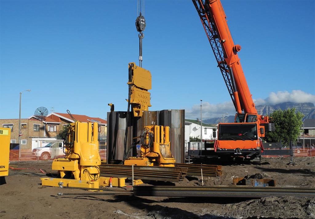
The execution of the wall would be done with standard equipment. As the project is in an urban area, noise and vibrations due to the execution of the walls need to be addressed. For the steel sheet piles, a vibrationless driving equipment (hydraulic press) was preferred by the design engineer, which had a slight influence on the choice of the sheet pile profile.
The service life of the structure was assumed to be 100 years, during which no major maintenance or repair works would be required for any of the structural solutions, except for the renewal after 50 years of the fire protection painting required for the SSP and the secant pile wall.
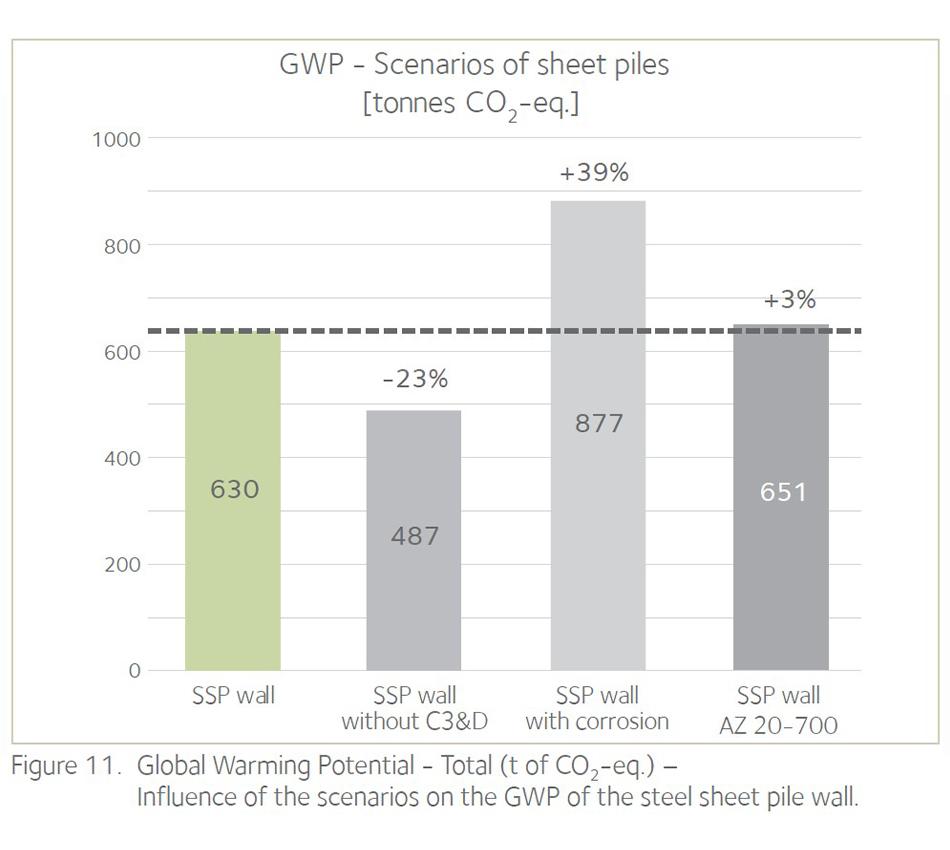
The basic scenario assumes that after the service life, the steel sheet pile wall can be fully recovered, whereas for the concrete wall solutions and the cutter soil mix wall dismantling is currently technically almost impossible. The main parameters that have an influence on the environmental impact after the installation phase are corrosion (loss of steel thickness), corrosion protection (coatings), carbonation of the concrete, as well as the reuse and recycling rates assumed at the end of life.
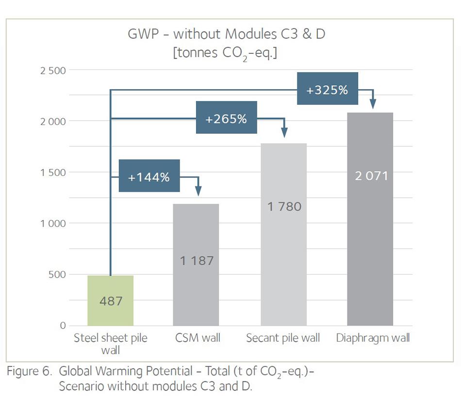
Consequently, a sensitivity analysis considered a variation of a few parameters, for instance:
- no deconstruction of any structure ⇒ exclusion of modules C3 and D;
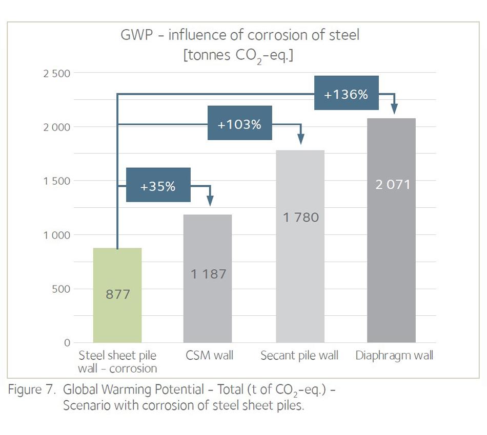
- loss of steel thickness due to corrosion;
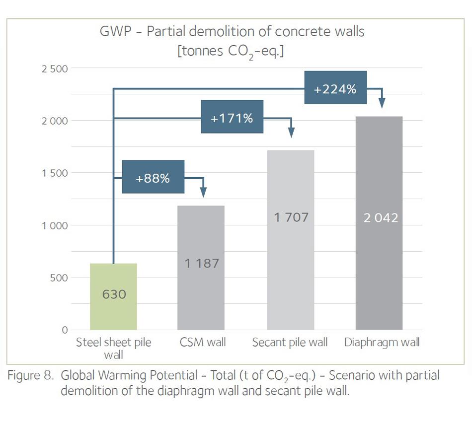
- recovering and recycling of a portion of the concrete wall (above the bottom slab level);
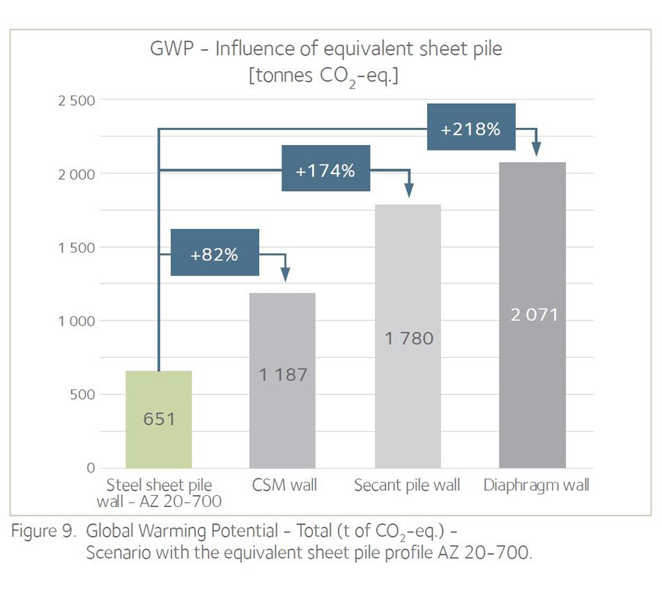
- influence of the choice of the sheet pile section;
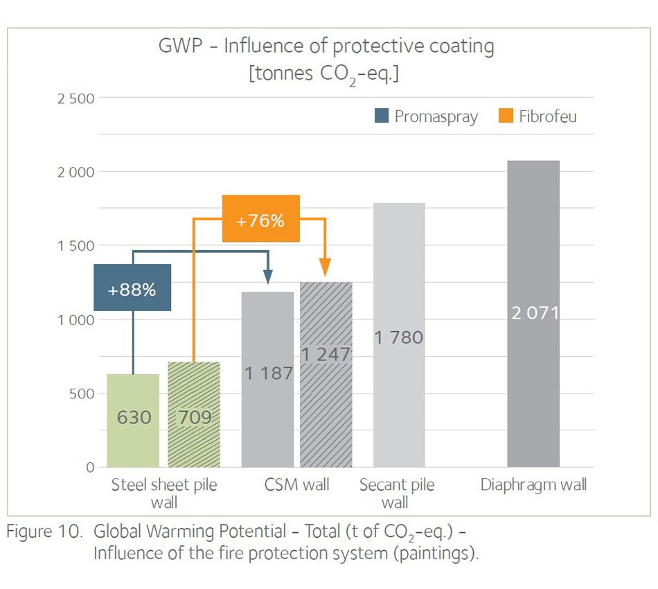
- influence of the fire protection product.
For the steel structure, sacrificial thickness was chosen, so no coatings were considered except for a fire protection spray coating on the exposed face. According to EN 1993-5, the loss of steel varies with the exposed zone, but in the Netherlands, it is usual to refer to the CUR 166. The maximum loss assumed per face is 0.012 mm/year in the buried zone.
Use of low carbon cements was not analysed in this case study because the allocation method for this product was under discussion at the European level at the time where the LCA was drafted.
The impact of bentonite was neglected due to the lack of reliable information available.
Environmental indicators
The different environmental impacts are characterized according to EN 15804 based on CML 2001. For the steel Environmental Product Declaration (EPD), “CML 2001: April 2013” has been applied, following EN 15804+A1 and IBU PCR Part A. For the concrete EPD, the same framework is applied.
For non IBU data, the extraction from the database Gabi is done with the same EN 15804 method. Only the date of CML 2001 method could vary but that would only slightly influence the results. Thus, this study can be considered as a carbon footprint assessment. GWP remains the most convenient indicator to quantify CO2-eq. emissions. This indicator is calculated according to EN 15804 (23 flows) based on CML 2001: April 2013 method (235 flows) based on IPCC 2007. For all steel data, a physical allocation is applied to slag according to the EUROFER rules.
Functional unit
The LCA covers the entire underground car park (250 m x 30 m) and its effects over a time horizon of 100 years, the assumed lifetime of the structure.
The different retaining structures fulfil the requirements of a retaining wall (horizontal loads from the soil) and a bearing foundation (vertical loads from the structure).
Methodology
Transport
The environmental impact of the transport modes is taken from the Gabi database from 2018. It contains several categories for each transport mode, for instance an “articulated lorry with a maximum payload of 27 tonnes, Euro 0-6 mix”.
The LCA considers following assumptions for the transport
- steel sheet piles: 410 km by rail – from the mill in Belval (LU) to Amsterdam (NL);
- rebars: 1 400 km by rail - average distance from the mills considered in the EPD to Amsterdam;
- steel H-beams: 410 km by rail – from the mill in Belval or Differdange (LU) to Amsterdam (NL);
- concrete: 10 km by truck - from a batch plant close to the jobsite in Amsterdam.
End of Life practices
Generally speaking, steel sheet piles are recovered after the temporary use, respectively after the service life. In the EPD EcoSheetPiles, the chosen assumptions are that 25 % are reused, 74 % recycled and 1 % landfilled. However, in the case of a UCP, it is quite rare to reuse sheet piles that have been used in a permanent wall for 100 years, hence the basic scenario considers that the sheet piles will be extracted and recycled after the service life. The more realistic end of life scenario is
- 99 % recycling, 0 % reuse and 1 % landfill.
The method used to adapt the values from the EPD to above scenario is explained in detail in the report.
In the basic scenario, the three concrete solutions are not demolished at the end of life, but one additional scenario deals with this topic.
Bill of materials
The bill of quantities that was used for the analysis is detailed in the LCA report (please refer to the report for more details). It comprises following items
- equipment mobilization and demobilization,
- preliminary works, clearance and construction site requirements for the concrete solutions,
- material quantity and specifications,
- earthworks and temporary works,
- structural works,
- disposal of (construction) material.
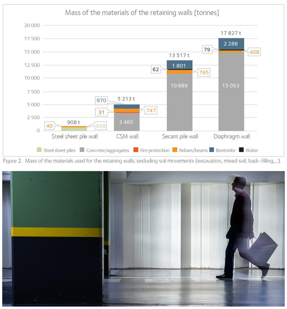
As can be seen on Figure 2, there is a significant difference on the total mass of the materials used to build the retaining walls, varying from a factor around 5 to almost 18. Although it can have a significant influence on the results, the mass is not considered as an environmental criterion. The criterion consists in multiplying each mass with the value of an environmental indicator, and to sum it up.
However, the more material you need to deliver to the job-site, the more traffic will be generated, and in urban areas, it may increase traffic congestion and lead to significant traffic jams, which has a substantial impact on the economy and the well-being of people living in the area. For this reason, choosing prefabricated light and compact elements may be an environmental judicious choice too.
System boundary
The environmental impacts are calculated considering the following phases:
- production of material, phase A1 – A3;
- transportation, phase A4;
- construction, phase A5;
- end of life, including demolition and processing, phase C3;
- benefits / loads beyond the product system boundary, phase D.
Phases B are not included since they are assumed to be negligible in this infrastructure application, except for phase B4 that considers the replacement of the fire protection coating after 50 years.
Note that phase A5 includes the construction site preparation. To distinguish “site preparation” and “material installation”, both parts have been separated into:
- A5 site preparation;
- A5 installation.
However, due to a lack of reliable data and information on the execution methods, for A5, only the supply of bentonite and the site preparation (excavation) are included. No other installation processes are considered since not enough precise scenarios could be provided. Hence, following elements were not considered in the LCA calculation:
- steel sheet pile scenario;
• diesel consumption of equipment to install and to remove the sheet piles. - concrete scenario;
• treatment of water to separate the bentonite;
• disposal of separated bentonite.
Consequently, to be coherent, phases C1 and C2 were also excluded.
Note: according to the EFFC DFI Carbon Calculator and some internal studies, an estimation of the installation processes contribution to Global Warming Potential is around 2 % for a steel sheet pile structure and 10 % for a concrete based structure.
Results
The focus of the LCA is on the Global Warming Potential. In the basic scenario, the sheet pile wall shows the lowest environmental impact. Compared to the second most environmentally-friendly solution, the CSM (soil mix), the difference of 88 % is pretty high.
The split into the different phases is shown in Figure 5.
The biggest gap between both solutions is observed in the phases A1-A3, in favour of the EcoSheetPile steel sheet pile solution.
The burden in module D of the EcoSheetPile structure can be explained as follows: the manufacturing of steel in an Electric Arc Furnace (EAF) requires more scrap than the quantities of recycled material available at the end of the life cycle. Using the methodology recommended by the Worldsteel Association, this leads to a negative “Net Scrap Value” and creates a burden, hence a positive emission of CO2-eq.
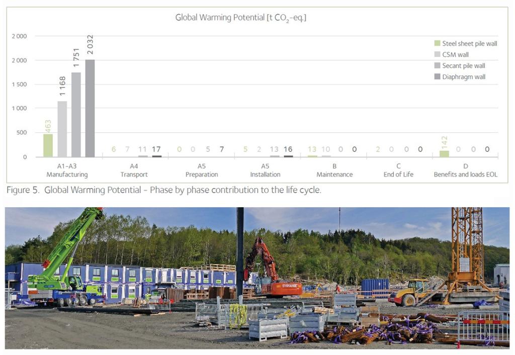
Moreover, the contribution of phases A1-A3 to the whole life cycle is more than 70 % in all the cases (around 70 % for the sheet pile solution, around 90 % for the concrete solutions and the soil mix).
Additional indicators were analysed: Acidification Potential, Abiotic Depletion Potential Elements, etc. Please refer to the report for more details. The trend is similar to the GWP for the additional indicators, except for the Ozone layer Depletion Potential where the environmental impact of the steel solution is higher, mainly due to the fire protection painting layer.
The comparison of the indicators shows a sufficient difference between the four alternatives to justify the statement that “the environmental impact of steel sheet piles is lower than that of other solutions”. Indeed, assuming a 5 % uncertainty on each input of the study, a difference of minimum 10 % is essential to demonstrate a clear difference between alternative solutions. This condition is observed for the indicators that were analysed.
Sensitivity analysis
Conclusions of the LCA
Conclusions
The aim of this Life Cycle Assessment (LCA) was to compare the environmental impact of several alternatives for the execution of the retaining wall of an underground car park (UCP) in an urban area. The design of a specific case study was performed by the Dutch design engineering firm Witteveen & Bos, assuming the structure would be built in the city of Amsterdam (NL). Although the LCA focused on the Global Warming Potential (GWP), other environmental indicators were examined, and a sensitivity analysis of key parameters was also done.
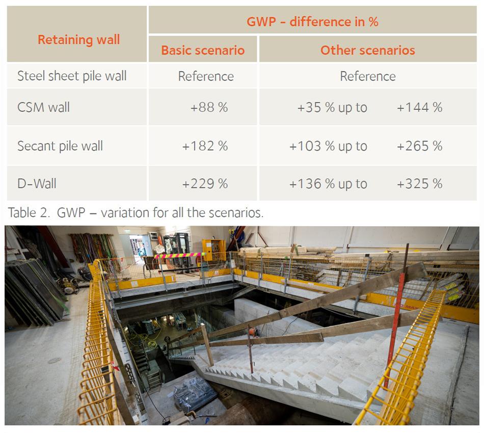
The key conclusions of this LCA for this specific case study is that the underground car park executed with a steel sheet pile retaining wall has a much lower carbon footprint (expressed in emissions of CO2-eq.) than equivalent alternatives in concrete (diaphragm wall, secant pile wall) and a deep soil mix wall (cutter soil mix). In the basic scenario the minimum difference is 88 % and varies for additional scenarios from +35 % up to +325 %.
Compared to the concrete solutions (D-Wall, secant pile wall) and to a cutter soil mix wall, the carbon footprint of the EcoSheetPile™ solution (SSP) is by far lower. In the basic scenario the minimum difference is 88 %
Limitations
It is important to note that from a technical point of view, all the four retaining wall solutions are equivalent. They have been designed by Witteveen & Bos to perform at a similar safety level during the whole service life.
The results and conclusions from this Life Cycle Assessment (LCA) illustrate a specific case study, and they cannot be extrapolated to other situations (i.e. soil conditions, countries,…) without further analysis (no generalization of the conclusions). The LCA is a snapshot of a specific space and time combination, based on EPDs available at the time of analysis. Technology can evolve quite fast.
The LCA focuses on the environmental indicator Global Warming Potential (GWP), which highlights the greenhouse gas emissions of the solutions, but other relevant indicators and / or technical aspects may lead to different conclusions on the most environmentally-friendly and sustainable solution.
Specific site or local conditions may have larger influence on the results in other situations. Particularly, transport to more remote locations may increase the contribution of Module A4, and although its contribution to the total GWP is in many cases quite small, it must be checked. Local conditions such as shortage of sand, potable water, aggregates, etc could create a more unfavourable situation for the structures using large quantities of concrete, and could lead to a higher influence of the transport module for instance.
Finally, some elements (processes or materials) have not been considered in the LCA. Please refer to the system boundary description in previous chapters, or to the LCA report for more details. This omission is basically due to the fact that the assumptions would be too gross, but based on past experience and available literature, these parameters would not reduce significantly the difference of the GWP between the steel and concrete solutions and would not change the conclusions.
As a reminder, the execution of the retaining walls has not been considered in the phase A5 due to a lack of reliable data. For instance, the influence of the driving of steel sheet piles will depend mostly on the chosen driving equipment. A rough estimation with a third-party calculation tool lead to a contribution to the GWP of only 2 % for the steel sheet piles, and 10 % for a diaphragm wall. This contribution is quite small, in the same range as the transport module A4, and hence would not change the conclusions.
References
- Witteveen + Bos, “Underground Car Parks Design - Ref. 111629/20-002.313,” Deventer, 2020.
- ArcelorMittal Global R&D, LCA methodological report - Comparative study of Steel Sheet pile, Diaphragm wall, Secant Piles and Cutter Soil Mix walls in Underground Car Parks application, Luxembourg, 2020.
- TNO innovation for life, “Review letter LCA UCP - Ref. 100339373,” Utrecht, 2020.
- Stichting Bouwkwaliteit, Determination Method - Environmental performance - Buildings and civil engineering works, Rijswijk, 2019.
- ISO, ISO 14040:2006-07 - Environmental management - Life cycle assessment - Principles and framework, 2006.
- ISO, ISO 14044:2006+A1:2018 - Environmental management - Life cycle assessment - Requirements and guidelines, 2018.
- CEN, EN 15804:2012+A1:2013. Sustainability of construction works. Environmental product declarations. Core rules for the product category of construction products, Brussels, 2013.
- CEN, EN 15978:2011. Sustainability of construction works. Assessment of environmental performance of buildings. Calculation method, Brussels, 2012.
- CEN, EN 1997-1:2004+A1:2013. Eurocode 7. Geotechnical design. General rules, Brussels, 2013.
- CEN, EN 1993-5:2007. Eurocode 3. Design of steel structures. Part 5: Piling., Brussels, 2007.
- CEN, EN 1992-1 (series). Eurocode 2. Design of concrete structures, Brussels, 2004-2019.
- CROW, CUR 166 Damwandconstructies, Ede: CROW, 2012.
- IBU - Institut Bauen und Umwelt e.V., PCR for Building-Related Products and Services. Part A - Calculation rules for the Life Cycle Assessment and Requirements on the Project Report - v 1.7, Berlin, 2018.
- Thinkstep (Sphera), Gabi database, Berlin, 2018.
- IBU - Institut Bauen und Umwelt e.V., EPD “EcoSheetPiles™” - EPD-ARM-20180069-IBD1-EN, Berlin, 2018.
- Nationale Milieu Database, 2021. [Online]. Available: https://milieudatabase.nl/. [Accessed 2021].
- Ecoinvent, 2021. [Online]. Available: https://www.ecoinvent.org. [Accessed 2021].
- EFFC - DFI, EFFC DFI Carbon Calculator Methodological & User Guide v2.1, 2013.